![]()
|
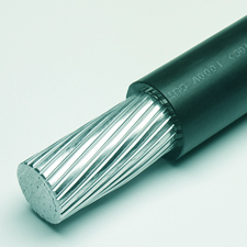
Single
aluminum conductor with extra thickness of low temperature moisture
resisting cross-linked polyethylene insulation. Rated 1000 volts. |
| ECS Catalogue Number | Conductor | Insulation (inches) |
Ampacity (30°C
Ambient) Free Air |
Ampacity (30°C
Ambient) Conduit# | Nominal O.D. (inches) | Total Weight (lbs/km) | ||
|---|---|---|---|---|---|---|---|---|
| No. | AWG Size | Stranding | ||||||
| RWUA08ST | 1 | 8 | 7 Strand | .080 | 45 | 30 | .31 | 131 |
| RWUA06ST | 1 | 6 | 7 Strand | .080 | 80 | 55* | .35 | 177 |
| RWUA04ST | 1 | 4 | 7 Strand | .080 | 105 | 65 | .39 | 243 |
| RWUA03ST | 1 | 3 | 7 Strand | .080 | 120 | 75 | .42 | 285 |
| RWUA02ST | 1 | 2 | 7 Strand | .080 | 140 | 95* | .45 | 341 |
| RWUA01ST | 1 | 1 | 19 Strand | .095 | 165 | 105 | .52 | 436 |
| RWUA001ST | 1 | 1/0 | 19 Strand | .095 | 190 | 120 | .56 | 525 |
| RWUA002ST | 1 | 2/0 | 19 Strand | .095 | 220 | 145 | .60 | 630 |
| RWUA003ST | 1 | 3/0 | 19 Strand | .095 | 255 | 165 | .65 | 761 |
| RWUA004ST | 1 | 4/0 | 19 Strand | .095 | 300 | 185* | .71 | 922 |
| RWUA250ST | 1 | 250 | 37 Strand | .110 | 330 | 215 | .79 | 1,108 |
| RWUA300ST | 1 | 300 | 37 Strand | .110 | 375 | 240 | .84 | 1,289 |
| RWUA350ST | 1 | 350 | 37 Strand | .110 | 415 | 260 | .89 | 1,473 |
| RWUA400ST | 1 | 400 | 37 Strand | .110 | 450 | 290 | .94 | 1,650 |
| RWUA500ST | 1 | 500 | 37 Strand | .110 | 515 | 330 | 1.02 | 2,001 |
| RWUA600ST | 1 | 600 | 61 Strand | .125 | 585 | 370 | 1.13 | 2,411 |
| RWUA750ST | 1 | 750 | 61 Strand | .125 | 670 | 405 | 1.23 | 2,933 |
| RWUA1000ST | 1 | 1000 | 61 Strand | .125 | 800 | 480 | 1.38 | 3,793 |
|
Colours: Standard colours are available. Non-jacketed RW-90 (XLPE) cables are not suitable for installation in vaults and switch rooms under the conditions of C.E. Code Part 1 Rule 12-2204. Suitable flame retardant jacketed cables are available on request. *For 3-wire 120/240 and 120/208V residential services or sub-services, the allowable ampacity for sizes #6, #2 and #4/0 AWG aluminum shall be 60, 100 and 200 amperes respectively. #2/0 AWG copper shall be 200 amperes. In these cases, the 5% adjustment per C.E. Code Rule 8-106(1) cannot be applied. # Based on not more than 3 copper or aluminum conductors in raceway or cable. For 1 conductor per underground duct installation ampacities see below. Applications: Parallel Cable ConfigurationsRecommended
Configurations
|
| Size | 1Cable/Phase ABC 7.5" OOO |
2Cable/Phase ABC CBA OOOOOO |
2Cable/Phase ABC CBA 24" OOO OOO |
4Cable/Phase ABC CBA OOOOOO OOOOOO |
4Cable/Phase ABC CBA 24" OOO OOO OOO OOO |
6Cable/Phase ABC CBA OOOOOO OOOOOO OOOOOO OOOOOO |
6Cable/Phase ABC CBA 24" OOO OOO OOO OOO OOO OOO |
|---|---|---|---|---|---|---|---|
| CU AL | CU AL | CU AL | CU AL | CU AL | CU AL | CU AL | |
| 1/0 | 295 230 | 267 208 | 275 215 | 203 158 | 220 171 | 165 129 | 179 140 |
| 2/0 | 335 265 | 302 235 | 310 245 | 229 178 | 248 193 | 186 145 | 202 157 |
| 3/0 | 385 300 | 341 266 | 355 275 | 258 201 | 280 218 | 210 163 | 228 178 |
| 4/0 | 435 340 | 386 301 | 400 310 | 291 227 | 315 246 | 236 183 | 256 200 |
| 250 | 470 370 | 421 328 | 435 340 | 317 247 | 343 267 | 256 200 | 278 217 |
| 350 | 570 445 | 500 390 | 520 410 | 375 292 | 408 318 | 304 237 | 331 258 |
| 500 | 690 540 | 605 471 | 630 495 | 452 352 | 489 383 | 365 284 | 396 309 |
| 600 | 752 590 | 659 513 | 682 541 | 491 382 | 534 419 | 397 308 | 433 340 |
| 750 | 845 665 | 745 580 | 775 610 | 554 431 | 596 469 | 447 348 | 482 379 |
| 1000 | 980 780 | 846 659 | 890 710 | 627 488 | 683 542 | 505 393 | 551 437 |
| 1250 | 1083 868 | 935 750 | 985 790 | 691 554 | 753 604 | 556 446 | 607 487 |
| 1500 | 1176 952 | 1011 821 | 1068 865 | 746 605 | 813 660 | 600 487 | 655 531 |
| 1750 | 1257 1027 | 1078 880 | 1140 932 | 793 647 | 865 706 | 637 520 | 696 568 |
| 2000 | 1325 1094 | 1133 934 | 1200 991 | 832 686 | 909 749 | 669 552 | 730 602 |
|
Notes Neutral conductors to be located outside of the above groups in the most convenient manner. |
